
‘Tis the Season to be Jolly

A gift from me to you
*pages of FREE navigation tips, tricks ideas & advice*
Be safe & have a wonderful Christmas & New Year – fair winds.
I read a great FB post this morning on how a cruiser found that different range scales on their electronic charts meant different information being shown. More critically, some hazards were not shown on a small scale.
- This, of course, goes for paper charts too.
- It is a great reminder that we shouldn’t rely on ONE navigation tool
- And that is just what they are – tools – nothing comes with any guarantees!
This time of year is a time we should:
- Be safe and
- Give to others
So here is a good chunk of Navigation information from our book Cruisers’ AA

Remember
- Electronic chart errors are not the only equipment that comes with errors
- There are GPS errors (both human and in the unit!)
- Paper-chart errors
- GPS is only as accurate as the chart it relates to
- This is stuff, we all need to know
There is lots more free information included, (below) – copy & paste if you wish. Also, HERE, you will find more great navigation diagrams and pictures.
A little bit about Cruisers’ AA
- There are 235 A4 pages crammed full of tips, tricks, ideas and advice on living on board & cruising
- In the Navigation Section alone there are 53 A4 pages of great advice to help keep you safe.
- There are pictures, diagrams, short stories & articles
- Below are FREE Navigation notes from Cruisers’ AA,..
- and so much more….. just scroll down…
You can now buy the complete book for $3.99 on Kindle.
So, for the price of a cup-or-two- of coffee, you could be better equipped to sail and more importantly be safe.
(At the very end of this post, see the list of additional information included within the complete Navigation Section of Cruisers’ AA).
NAVIGATION
Bearings
Three bearing fix: This is a great way to double check your position.
On your chart select three conspicuous landmarks to use, to avoid large errors when underway. Take a bearing with your hand compass of the landmark closest to your stern first, then closest to your bow, and finally, the one that is abeam (090° from your bow).
You must be 100% sure that you visually identify the correct landmarks and, ideally, the landmarks should be around sixty degrees apart.
You will need to apply Compass error (Variation), but no Deviation if using a hand held compass (Deviation is only applied if you are using the ship’s compass and you know the Deviation).
Compass errors (Variation and Deviation): The difference between True North and Magnetic North is called Variation. The degree of Variation and its annual rate of change is indicated on nautical charts within the Compass Rose. Deviation is the deflection of the compass from its proper orientation. It is usually caused by magnetic materials on the boat (or indeed the boat itself). Deviation can be east or west, or zero, depending on the magnetic conditions on the vessel. The value will change with the boat’s heading. (See ‘Compass: True to Compass’ further on in this section.)
Once you have converted the Compass bearing to a True bearing, plot the bearings on your chart. Where the three bearing lines cross, is your fix position. The time of the bearings taken is noted on the chart next to your fix position. This is very important, especially when using DR. (See ‘Position – DR’ in this section – Ded Reckoning is actually ‘Deduced Reckoning’.)
Do not use navigation buoys for bearings, as they may have moved from the charted position.
You can take just two bearings, but they will not show any errors that may have occurred, as three bearings will.
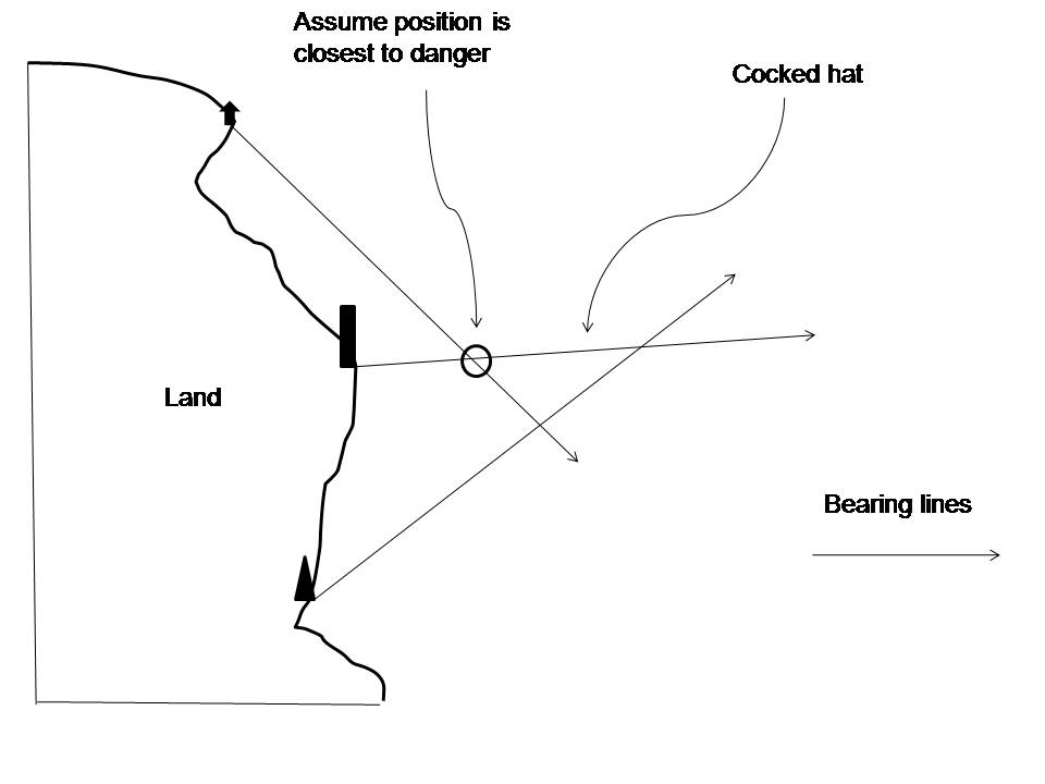
With three bearings, you may end up with a cocked hat where the three bearing lines meet (usually looks like a witch’s hat, see picture below). If it is not too big, mark your position in the cocked hat at the closest point to danger and have another go (in the example below, that position would be nearest to land). Cocked hats occur with errors (plotting, wrong identification of object, compass error incorrectly applied or unknown compass error), or this could occur with the imprecise reading of the compass or an unsteady hand when at sea.
(More diagrams here)
Radar bearings: These are not as accurate as radar ranges as the boat is often yawing, but it is good practice to use several methods to confirm your position (other than using the Global Positioning System).
The horizontal beam from radar produces a certain width (called the horizontal beam-width) and this will change the bearing by a few degrees. The wider the scanner, the narrower the beam-width and therefore the more accurate it is.
In Heads Up mode, simply use the EBL (Electronic Bearing Line) on your radar to obtain the Relative bearings on screen. Remember, only TRUE bearings can be drawn on your chart.
To convert the Relative bearing to a True bearing add your TRUE course to the Relative bearing. This is then the True bearing of the object or target and can be laid off on your chart.
True bearing (of object or target) = own ship heading (True), plus Relative bearing (of object or target).
Relative bearings: These mean they are Relative to the ship’s head. Relative bearings are different from Red and Green bearings. Relative bearings range clockwise from 000° to 360°; Red and Green bearings range from 000° to 180° on either port (Red) or starboard (Green) side. Relative bearings are easier to convert to True.
Relative bearings: Looking straight over the bow = 000°, over the stern = 180°, port beam is 270°.
Red/Green Bearings: If a vessel is abeam on your starboard side, she is also ‘090° Relative’ or ‘090° Green’. If a vessel is abeam your port side, she is also ‘270° Relative’ or ‘090° Red’.
Convert Red and Green bearings to True (for chart work): If you have taken a Green bearing, add this to your ship’s True heading. If you have taken a Red bearing, subtract this from your ship’s True heading.
True bearing = Ship’s heading (T) + Green bearing
True bearing = Ship’s heading (T) – Red bearing
Note: If you end up with a negative number, just add 360, as we work within 360°.
E.g.
True bearing = Ship’s Heading (T) – Red bearing
= 054° (T) – 085° (Red bearing) = -031°
= -31 + 360
True bearing = 329°(T)
(Of course, if you can see you will end up with a negative number, you can add on the 360 first if you wish.)
Notes on radar: Relative motion Course-Up (stabilised) or North-Up (stabilised)
With the addition of heading information from the vessel’s electronic compass and/or GPS, the stabilised capable radar can provide True bearings. These True bearings can indicate the vessel’s True course and the target’s True bearing, and the effect of yawing is minimised on the screen.
Course-Up: display provides the more realistic view as the top of the screen is the direction of the ship’s heading and so targets viewed on the right hand side of the screen are seen on the starboard side of the wheelhouse.
North-Up: display relates directly to the view of a chart that is read north up. It will have a different orientation to the view looking out of the wheelhouse.
(See ‘Parallel Indexing’ further on in this section for more information on radar set up.)
Chart errors: If you are plotting on older charts you may find that the GPS co-ordinates put you on an island! In this case, the GPS is more accurate than the chart. All positions will need to be offset by the amount given in the title of the chart. Every modern chart will have a note stating whether the GPS co-ordinates can be plotted directly or an offset is to be followed. This is a good example that shows you must check all the information provided on the chart, very carefully. (See ‘GPS errors’ later on in this section.) Much older charts, prior to GPS, may have no information at all regarding GPS derived co-ordinates.
For example (1): Chart AUS 252 Whitsunday Group. Under the chart title it states:
SATELLITE DERIVED POSITIONS
Positions obtained from the Global Positioning System (GPS) in the WGS 1984 Datum can be plotted directly onto this chart.
Example 2: Chart AUS 802 Cape Liptrap to Cliffy Island, states:
Positions are related to the Australian Geodetic Datum (1966)
(see SATELLITE DERIVED POSITIONS Note).
Next to title it states:
SATELLITE DERIVED POSITIONS
Positions obtained from the Global Positioning System (GPS) in the WGS 1984 Datum must be moved 0.09 minutes SOUTHWARD and 0.08 minutes WESTWARD to agree with this chart.
Making the corrections: In the case of chart AUS 802 the correction would be as follows:
| GPS (WGS 1984) position | 39° 00.00ʹ S | 146° 15.00ʹ E |
| + 0.09ʹ S—————- | – 0.08ʹ W—————– | |
| 39° 00.09ʹ S | 146° 14.92ʹ E |
Corrections vary: Some South Pacific Island charts will note corrections that can be a nautical mile out!
Safety precaution: For an additional navigational safety precaution, learn how to Parallel Index using your radar. (See Parallel Indexing later on in this section.)
Measurements: A nautical mile is one minute of arc along a great circle of the earth, e.g. the equator. For chart work, we use Mercator projection. In Mercator projection, the correct scale for one nautical mile is one minute of latitude, measured off the latitude scale adjacent to the area you are working in.
Minutes are denoted by: ʹ (60ʹ = 1 degree)
Seconds are denoted by: ʺ (60ʺ = 1 minute)
Fathoms: 1 fathom = 6 feet (approx 1.83 metres). (See the Measurements & Conversions section for a comprehensive list of measurements and conversion formulas.)
Chart symbols: Carry an appropriate book on board to check what each of the symbols on your chart mean. We use Chart BA5011, as this book has all the symbols and abbreviations used on Admiralty charts. Here are some important examples:
Compass
The compass functions as an indicator to Magnetic North. The magnetic bar in the compass aligns itself with the earth’s magnetic field.
Compass Section also includes:
True North and Magnetic North
Cardinal points and steering
Points of a compass
True for chart work
True to Compass (or Compass to True)
Example – Compass to True
Deviation
Calculating Deviation
Variation
Calculating Variation
See more diagrams here.
GPS – Errors
GPS contains errors and therefore your position should always be checked via other methods. (See ‘Position fixing’ later on in this section.)
Errors that occur within the GPS unit:
- Systematic: Some errors are caused by the changing satellite geometry. This is called Dilution of Precision (DOP). For a three-dimensional fix, you need four satellites. Ideally, one of the satellites should be directly overhead, with the other three separated by 120 degrees of azimuth. An arrangement other than this ideal situation will cause DOP inaccuracy. A good value of HDOP (Horizontal DOP) is between two and four, values in excess of this size are of poor accuracy – you can check the values on the GPS.
- Environmental errors: Moisture and salt in the air, poor weather conditions or lightning.
- Ionospheric delay: Signals from satellites bend on entering the ionosphere (this is also known as refraction) and their speed varies. (The ionosphere is the outer region of the Earth’s atmosphere.)
- Multipath error: A satellite signal may be reflected off the water, or off metal objects on board your vessel. This may cause the GPS receiver antenna to receive the signal by two or more paths.
- Receiver errors: Mismatch of satellite signals.
- Selective Availability: SA is the military’s ability to scramble the GPS readings. At the time of writing, the USA is not scrambling the signal (the SA was turned off in 2000). DGPS (Differential GPS) was developed to reduce SA.
Common errors in using the GPS:
- Offset: The main position fixing error occurs when using the GPS in combination with older charts. The correct offset from the chart needs to be applied to the GPS reading (see ‘Chart Errors’ earlier in this section for full details).
- Ensure your GPS settings match the spheroid of your chart. The GPS is usually operated on a spheroid called World Geodetic Spheroid 84 (WGS84). In the past, charts have been based on various spheroids, e.g., Australian Geodetic Datum 1966 (AGD66). You must check your chart to find out whether it is based on WGS84 or AGD66 (for example) and set your GPS accordingly.
- Magnetic or True: You can select Magnetic or True settings for bearings and courses. Ensure you have selected your preferred setting before completing these calculations. (See ‘True to Compass or Compass to True’ under Charts, earlier in this section.)
- Measurements: Are you reading statute miles or nautical miles for distance? Check your unit is set to nautical miles.
- Measurements: Are you reading knots for speed? Ensure your GPS is set correctly.
- Measurements: To reduce errors, check your GPS is set to degrees, minutes and decimals of a minute instead of seconds – to match your charts.
- Location: Follow the manufacturer’s instructions when mounting your GPS. Obstructions can affect the signal and the GPS unit can affect the ship’s compass.
- Input Errors: Double check the co-ordinates that have been inputted by you into the GPS. Ask someone else to read and check the numbers too.
Latitude & Longitude
Writing latitude and longitude correctly is very important. The next person on watch must be able to read and understand what you have written on the chart and in the log book. Latitude should always be written first.
E.g.
00° 36ʹ 12ʺ S
080° 25ʹ 42ʺ W
Written above is: degrees (°), minutes (ʹ) and seconds (ʺ). There are sixty minutes in a degree and sixty seconds in a minute. You can instantly spot an error if the minutes (ʹ) or seconds (ʺ) are sixty or higher. The highest number of minutes that can be used is fifty-nine. (001° = sixty minutes, therefore 000° 61ʹ is written incorrectly and should be written as (and is the same as) 001° 01ʹ.
Seconds can be written as decimals of a minute. This makes it possible (and easier) to use a calculator. For example, the above latitude and longitude would be written:
00° 36.2ʹ S
080° 25.7ʹ W
0.1 of a minute is 6 seconds, therefore:
12 seconds is 0.2 of a minute and 42 seconds is 0.7 of a minute.
To convert:
To convert seconds to decimal divide the seconds by 60.
To convert decimal to seconds multiply decimal by 60.
0.1 of a minute x 60 = 6 seconds.
Therefore 0.1 of a minute is 6 seconds.
To calculate the Lat./Long. examples above:
12 seconds to decimal of a minute: 12 / 60 = 0.2
42 seconds to decimal of a minute: 42 / 60 = 0.7
Our charts are in degrees, minutes and decimals of a minute and our GPS is set the same. To reduce errors, set your GPS to match your charts. (See ‘GPS Errors’ earlier in this section.)
(See Measurements & Conversions section for more calculations and all the decimals of an hour.)
Patience
Short story Thirty miserly minutes too late: We arrived at Bahia de Caráquez, Ecuador at 6a.m. The ‘waiting room’ co-ordinates were spot on (this was an anchor spot outside the main channel where we had to wait for a pilot). On VHF we called ‘Puerto Amistad, this is the sailing vessel Pyewacket II’. The radio stayed as silent as the calm sea; at 7a.m. it crackled into life, but by then we had missed the necessary high tide by an impossibly tiny 30 minutes. The entrance into Bahia de Caráquez was through an unmarked channel, uncomfortably close to the shoreline and shallow in places. It was cheap insurance, at US$30, to hire a pilot. Anchoring in the exposed ‘waiting room’ was our only option. For twenty-three hours we impatiently waited for high tide and daylight to synchronise. With visions of upping anchor during the night while riding the building swells, we tried to sleep in the afternoon. The 2,800 nautical miles from Acapulco (via a brief stop at Isle de Cocos) had taken its toll. Dirty-steel coloured water beneath persistent squalls and looming breasts of black clouds streaked with lightning had been our consistent company for too long! But even though we were close to the end of the trip, we had to be patient.
Position Fixing
Fixing your position can be done several ways besides using your GPS. Batteries can fail and GPSs can break and have errors (see GPS errors earlier in this section). Have some handy position fixing tricks up your sleeve.
To take a fix, always note the time the fix was taken. This is imperative for DR (Deduced Reckoning – read on for full information). It is fun to experiment with different ways to check your position, especially when coastal cruising. (See ‘Bearings’ earlier in this section for another way to check your position.)
Position: double the angle off the bow
This calculation takes advantage of the properties of an isosceles triangle. An isosceles triangle has two sides of equal length and consequently, it has two internal angles that are also equal. This rule is used when the second bearing between the bow of your boat and the target is double the angle of the first bearing.
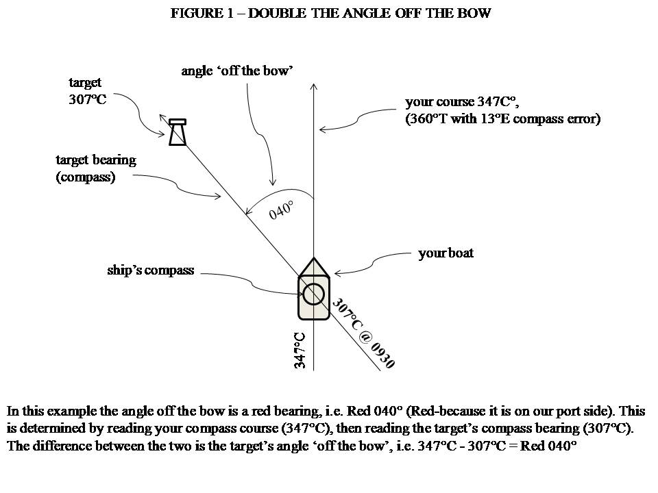
How to perform ‘double the angle off the bow’ on board: See Figure 1(below) for a complete depiction of what double the angle off the bow refers to. Your first angle off the bow needs to be between 020° to 045° (less that 020° can reduce accuracy). So how do you measure this?
See diagram on: https://jackieparry.com/pics/
Step by step: how to calculate distance off, using double the angle off the bow method:
- Take note of the compass course you are steering. In our example, the course steered is 347°C (see Figure 2).
- With your hand-bearing compass, or by sighting over your ship’s compass, take a compass bearing of the chosen target (a lighthouse makes a good target).
- Record this bearing, your log reading and the time. For example, Course = 347°C, bearing to Target (e.g. Nobby’s Head Lighthouse) = 307°C, Time = 0930hrs, Log reading = 0.
- The difference between course steered and the target’s bearing is the target’s angle off the bow. Study Figures 1 and 2.
While steering a steady course of 347°C an identifiable land target (Nobby’s Head Lighthouse) was sighted bearing 307°C.
Angle off the bow = 347°C – 307°C = 040°
As the target is on our port side, we can call this angle RED 040°. (See bearings in this section for a full explanation of Red and Green Bearings and Relative Bearings.)
- If our first angle off the bow = RED 040°, then doubling this angle will give us RED 080°.
- The compass reading required for the second bearing line to the target will equal the course steered minus the double the angle off the bow.
See Figure 2.
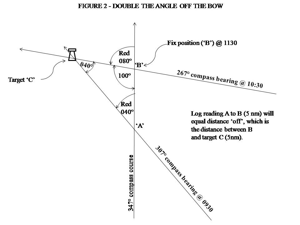
347°C – 080° = 267°C
- As you are proceeding along the chosen course (347°C), keep an eye on the target’s bearing. When the same target (Nobby’s Head Lighthouse) bears 267°C, note down (again) the time and distance run (from the log).
See Figure 2.
Course steered = 347°C, target bearing = 267°C, distance run = 5nm, time of second bearing = 1030hrs.
- The number of sea miles covered (assuming no current or leeway) equals the distance the vessel is from the target. So you can say, ‘At 1030hrs we are 5nm from Nobby’s Head Lighthouse, which is on a bearing line of 267°C.’
See more diagrams on: https://jackieparry.com/pics/
When you get the chance, have a go; it’s actually quite simple and straightforward.
Another useful method is to guess 045° off the bow using your arm. Swing your arm from pointing at the bow to pointing abeam of your boat. Half of this swing (090°/2) is 45°. When the target is 045° off the bow, note the time and log reading, double the angle off the bow will be 090° or abeam.
When target is abeam, note the time and log reading. As before, the distance run will equal your distance off the target.
This method is easier, but it is not predictive, i.e. you may have to avoid a danger that is lying off a headland. By using an initial angle off the bow less than 045° (e.g. 030°), you can predict your clearance off the headline on arrival. By using 045° as your initial angle, by the time 090° (abeam) comes up, you could be in the danger zone!
Remember: to be able to plot the fixed position on a chart, convert all bearings to TRUE. We have used a total Compass error for the above example of 13°E. So we have to add 13°E to all the Compass bearings to obtain the True bearing for the chart work.
The Isosceles Triangle – how does it help us?
Refer to Figure 2. A straight line (our course) = 180°. We cut that line with the double angle of 080°, therefore 180° – 080° = 100° remaining.
This 100° forms the angle at the top of our isosceles triangle.
All triangles have three internal corner angles. The value of all three angles added together always equals 180°.
In our example, we have 100°+ 40° = 140°. We know triangles have a total of 180° internally, therefore the remaining angle must = 40°. There it is: our isosceles triangle!
We have a base line of a triangle, A to C and the two remaining sides (A to B and B to C) are equal in length because we have an isosceles triangle with two equal internal angles.
If we know the length of one side (our course covered, A to B) from our log reading, we then know the length of the side B to C.
A to B = 5 nautical miles, therefore B to C = 5 nautical miles.
We are 5 nautical miles from the target at 1030hrs.
Position – DR
In navigation, Ded Reckoning (DR) is the process of calculating your position by using a previously determined fix. You advance your first fix based upon known or estimated speeds over elapsed time and course. You must maintain the same speed, time and course for the duration (note length of time) or calculate an average. Of course, set and drift (effects of current) need to be accounted for at times to provide an Estimated Position (read on for more information on Estimated Positions).
To rely on a DR position, you must ensure your first fix is correct. As the new calculation is based on this position, if it is wrong the errors will accumulate. For example, you have obtained a good fix and for an hour you have been sailing at 5 knots. During this time, you have travelled five miles through the water. If your course has been the same, simply extend your course line and mark off five miles (measure miles off the latitude scale nearest to your location). This is assuming no set and drift.
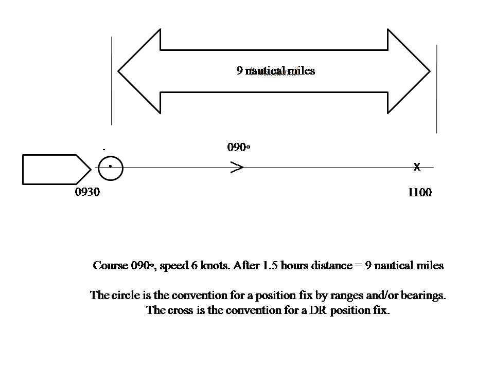
The following example is a vessel travelling at 6 knots for one and a half hours (see Speed, Distance, Time formula later in this section for more complex calculations).
See diagram on: https://jackieparry.com/pics/
In one hour at 6 knots you would travel six miles, in another half an hour you would travel another three miles, therefore over an hour and a half you would have travelled a total of nine nautical miles. (The DR position is marked with an X and the time noted.)Remember, this example does not allow for set and drift. Estimated Position (EP) is DR with estimated set and drift applied.
Reciprocal Bearings
If you have reciprocal dyslexia, an easy way to calculate the reciprocal bearing is to plus or minus 200, then adjust by twenty accordingly. For example, for the reciprocal of 050°, add 200° = 250°, then just minus 20° = 230°.
Wind – Apparent & True
When your boat is moving, the wind indicator (or your wetted thumb) shows ‘apparent’ wind. This means that the direction and strength of the wind includes your movement, i.e. if you are going downwind, the wind feels less, but if you are going into the wind, it feels stronger. True wind is the actual force of the wind if you were stationary. Try to give your True wind when talking to other boats.
Wind vectors: See diagram on: https://jackieparry.com/pics/
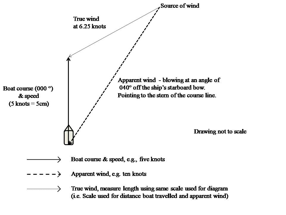
Step by step: how to calculate true wind:
- Draw a line representing your True course and speed, for example: course 000° T, speed 5 knots. Choose a scale to use, say 5 centimetres for 5 knots (one cm per knot).
- Place an arrow at the head of the line where your bow is pointing.
- Draw the apparent wind speed and direction, i.e. where the wind is blowing to, with the head of the arrow pointing at the stern of your course and speed line. In our example, that is approximately 040° off the ship’s bow at 10 knots, therefore the line would be ten centimetres long. (The drawing below is not to scale.)
- The True wind is the resultant vector drawn from the tail of the apparent wind line to the head of your vessel’s course and speed line.
- Measure the True wind line using the scale you have been using for the rest of the vector (in this example, measure how many centimetres the True wind line is, that will be your True wind speed in knots).
- Measure the angle of the True wind. You now have the True wind speed and direction.
Rules to follow
- Speed is always drawn to the same scale for each line of the vector.
- Direction is always drawn in the same type of bearing, e.g. True, Magnetic or Compass.
- True is best, then you can calculate the True wind (direction the vessel is going to and direction the wind is coming from).
- The head of the arrow must be placed at the head of the line, indicating direction.
- Apparent wind blows to your stern (on your course and speed line).
- True wind blows to your bow (on your course and speed arrow).
Additional Information included in the Navigation Section of Cruisers’ AA
AIS
Charts hint & tips
Collision
Col Regs
Electronics
True North and Magnetic North
Cardinal points and steering
Points of a compass
True for chart work
True to Compass (or Compass to True)
Example – Compass to True
Deviation
Calculating Deviation
Variation
Calculating Variation
GPS – Tracking Function
Hand-Bearing Compass
IALA International Association Of Lighthouse Authorities
Nav Lights
Reefs
Rounding Capes
Safe Water (Navigation)
Set & Drift
Sextant
Speed, Distance, Time Calculations
Speed
Speed vs. Wind
Waypoints
Weather At Sea
Navigation Hints
Parallel Indexing (or Blind Piloting)
Patience
Position – Estimated Position (EP)
Position – Running Fix
Position: Correct Chart Work & Symbols
Protractors & Parallel Rulers
Position – Radar
Radar Reflector
Of Foreign Build – From Corporate Girl to Sea-Gypsy Woman…. read the first few chapters FREE here…..
Cruisers’ AA – Accumulated Acumen…. read the first few chapters FREE here….
Image courtesy of Danilo Rizzuti at FreeDigitalPhotos.net
