Steering By A Star
by Jackie and Noel Parry
I suspect that if it is your personal aphrodisiac to hand steer, you sail for short periods. Connecting with nature through steering gear is admirable. From time to time I like to hand steer . . . out of port. Once clear of land Roy takes over. Roy is our Aries wind vane, named after my dad who assisted Noel in scraping off the decades of salt, lubricating and fitting new bearings; allowing the $US300 ($AUS347) seized Aries to flex his muscles and get to work.
While ‘Roy’ attended fittings, fellow cruisers tossed a few sceptical looks our way, which we refused to catch. “You think the Aries will steer a 51’ boat?” Admittedly, a toredo of doubt had wormed its way into my thoughts. The enigma compounding these concerns was connecting the Aries to hydraulic steering and operating the vane from the centre cockpit.
With ‘Roy’ fully limbered up, Dad and Noel measured up the required Aries support frame out of tubing. Then Noel and I commenced search by ‘phone and many miles on pushbike to find a fabricator to help fabricate the frame. A week later we changed tack and embarked on an oratorical fiesta searching for an electric welder large enough to handle our proposed projects and small enough to afford (in both dollars and power) and stow. Noel had pondered the problems of the cockpit position and hydraulics and dialled up his ingenuity. Many moments I caught him gazing at the back of the boat trying to join the dots and ultimately creating an interesting overture. After many hours of internet searching, hoping someone had simply written up the answer, it seemed the emergency steering was the way to go. It meant much welding; weighing up the cost of paying a fabricator and buying a welder resulted in a new crew member in the form of an 110v/240v arc welder.
Onboard Pyewacket II, the design of the emergency steering places the helmsman in the aft cabin, standing in a dark room, staring at him/herself in the full length mirror; the only visibility to the outside world being the side and rear port holes. The rudder stock is directly below the stairs that lead to the boot (aft cockpit), which is the reason for the obscure positioning of the helmsman. Above the stairs is a hatch. To connect the Aries to the rudder stock we had to extend the length of the rudder stock up through the stairs and through the hatch and to this extension fabricate a ‘wind vane tiller’. We also had to find a way to quickly and easily turn the by-pass valve, to bypass the hydraulic steering.
Holes were drilled into the hatch to allow an extension from the rudder stock up to the after cockpit, leaving the sliding door closed (or open if we wished). Noel welded the emergency tiller arm onto the wind vane tiller (that in turn, was bolted onto the extended rudder stock). The emergency tiller is at an angle to allow us to stand on the seat in the aft cockpit. This gives us a much better view of the entire boat. Our last boat was tiller steered, but this is not quite the same. The emergency tiller on Pyewacket II runs aft, instead of forward, it is, in effect, backwards. So to steer to starboard we push the tiller to starboard. Despite a little bit of wandering during practice, we’ve finally nailed it and are chuffed to have this steering available should the main hydraulic steering decide to opt for early retirement.
The Aries can easily be attached to the ‘wind vane tiller’. The ropes that run from the Aries are attached to chains, which in turn, slip over the tabs welded on the arms of the wind vane tiller. It is recommended that where the Aries ropes connect to the tiller in use, they should be 600-900mm from the rudder stock. The distance on our set up is only 450mm, in order to clear the life raft. Adding a block roved to advantage on each line has halved the effort and in effect, lengthened the tiller.
The lines to adjust the Aries (directionally) run into the centre cockpit, so changing course is simple. The bypass valve was not so simple. Flaunting its conceptual imperfections sitting under the aft cabin stairs is the hydraulic bypass valve and relief valve. All hydraulic systems incorporate these two valves. The relief valve comes into action if the rudder is put under an unexpected load, for example being hit by a large wave or a grounding. The bypass valve is just that, to bypass the hydraulics and must therefore be utilised when using the emergency tiller steering (and, in our case, the Aries). To add to the complexity, once the emergency tiller is in place we cannot lift up the stairs (to access the valve) without a complete dismantle of the system. Also, the bypass valve neatly sits under the hydraulic hoses. Enter: remote spindle. Noel made a kind of crankshaft to go around the hydraulic hose obstacles, drilled another hole in the stairs and hatch and created a remote spindle to turn the hydraulic bypass on and off. This we can operate from both cockpits. I tell Noel I think he is a genius; he simply shrugs his shoulders and says he is not the first to do this. It is the first contraption of this type I have seen and I am impressed. It means I can sit and write (as I am doing right now) while ‘Roy’ merrily steers our course (Noel is currently tinkering with a dickey regulator), any adjustments are just an arm stretch away.
As with most operational systems onboard there is a compromise. Catching a fish and hauling it in the aft cockpit does now require a certain amount of limbo dancing and partaking in a boat ‘twister’ game. Successful cruising is about finding a solution and accepting compromise. Whether cleaning dishes in a storm, reefing the main downwind or connecting conventional self steering to an unconventional set up. We are fortunate to have an aft cockpit where all the lines are situated, out of the way (mostly) but easily accessible. We are happy ‘wackets’ with hands free steering to pee and make tea at will.
Incidentally, the worm of doubt turned into fish bait. So far we have successfully tested ‘Roy’ in 8 to 40 knots of apparent wind. We are in no hurry to try him out in stronger winds and we are confident he will cope admirably as the Aries generally works better in stronger winds.
So now we steer by a star as the romantics prefer. However our ‘star’ is the wonderful ‘Roy’.
Personal observations
We find it imperative to have reliable self steering, ideally electrical and wind vane. We are ecstatic that the vane steers in such light winds. Our Wagner electric steering copes with calm seas, it is thirsty so it usually means we have the engine on.
The Aries website states that the Aries steers boat up to 50’. Our Aries has no problems with 20 tonnes and 51’.
Our second hand Aries model is quite dated, but very strong. New gears and bearings were purchased from England Helen Bell Franklin, (daughter of the Aries inventor, Nick Franklin), whom we had last spoken to in 1998 from a phone box in Southport, Queensland, Australia for our previous Aries parts onboard our last boat, Mariah II. Helen recommended that we purchase new cast stainless bevel gears. The aluminium gearing we currently had was, to quote Helen, “renowned for dissolving in mid ocean.”
We always set the Aries up before leaving port. Once set up we cannot open the hatch (we can open the sliding door). To enable fitting of the ‘new’ rudder stock, the hatch has to be completely removed in the assembly process. To do this we have fitted removable hinge pins.
An additional compass is now installed should we have to steer from our newly positioned emergency steering.
Maintenance and restoring
When first brought home, we laid the Aries on deck and poured penetrating oil on every conceivable, screw, bush and bearing; turning it over every couple of days to do the same on the other side, ensuring the oil soaked all the way through.
Replacement parts
The replacement stainless steel gears cost over £120 ($AUS205) (there are two), plus £90 ($AUS154) for the standard rebuild kit. But we figured that was still cheap for a working, reliable Aries. Our previous Aries steered us over 40,000 nautical miles in nine years across oceans and up rivers and canals using a connected auto pilot to the wind vane, and is still going strong with Mariah’s new owners.
Mounting
Mounting the Aries onboard Pyewacket II meant the transom door would be permanently closed. During long stays in port we can dismount part of the bolts and pivot the Aries out and use the transom door. So far climbing over the transom to the platform is easier. Noel considered mounting the Aries on a bridge over the door, but due to the strength and conglomeration of forces we decided against this idea. The compromises are small and the pay off large. The Aries is easily accessible from our swim platform and from the safety of behind the transom. Having the radar frame in place allowed us to dangle the Aries in position prior to bolting on.
We could have mounted the ‘wind vane tiller’ pointing aft and utilised a number of pulleys each side as a more conventional tiller steered boat (albeit in reverse). But that just seemed to clog up the back cockpit with more ropes and pulleys. That was why we decided to mount the tiller on top of the rudder stock athwartships, having the ropes leading directly from the Aries to the ‘wind vane tiller’. The head of the emergency tiller was welded on to the top of the ‘wind vane tiller’ at an angle, so we could steer from the seat in the cockpit and more easily see where we are going.
Alternatives?
We researched a clutch operated wheel drum for connection to the Aries ropes. They could be purchased for 200 Euros. This expense, the complexity of running pulleys to the centre cockpit, the problem of progressive creep* and the reliance on our thirty year old hydraulic steering, meant we opted for the idea of connecting the Aries directly to our rudder stock. We have successfully tested the transfer from Aries/emergency tiller, back to the centre cockpit hydraulic steering.
*Progressive creep can occur when wind vanes are connected to hydraulic systems. It simply means that you may have to continuously adjust the position of the ropes that lead onto the wheel clutch.
Additional adjustments
On our previous boat, Mariah II we connected an electric ram directly to the Aries which steered a fantastic course and consumed little power. The system never failed and continually held us on track saving us hours at sea in longer crossings. We eventually plan to set the same system up on Pyewacket II.
Emergencies
Everyone onboard a vessel should be aware of the emergency steering equipment, its location and how to operate it. The time to become familiar with the emergency steering is in a safe port or calm waters, not when you have just lost steerage and find yourself on a lee shore or crossing a bar.
Aries operation (courtesy of the Aries website)
When the yacht goes off course the plywood vane through its connecting linkage rotates the servo rudder from dead ahead. The water flow forces the servo rudder to one side pulling ropes which apply corrective helm to the tiller or wheel. The servo rudder has only to pull the steering lines to steer. It does not steer the yacht directly (the servo rudder does in fact assist the main rudder in its sideways thrust but only by a negligible amount).
The plywood wind vane has to be feathered ‘edge on’ into the wind by pulling on the course adjusting lines. When feathered correctly the vane is vertical or in line with the Gear. As the yacht goes off course the wind comes round on one side of the vane deflecting it from the vertical on its pivot shaft which in turn deflects the servo rudder from ‘dead ahead’ pulling the steering lines as previously mentioned.
Photos
OLYMPUS DIGITAL CAMERA
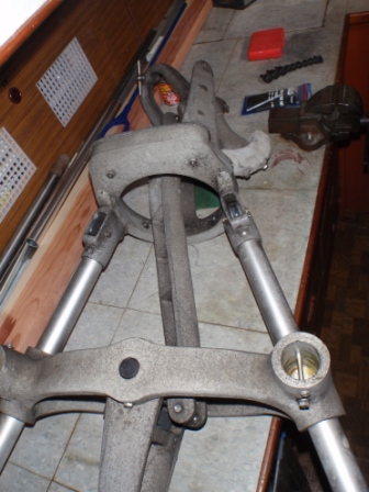
jparies1 – Aries assembly line (Roy forefront) and Noel.
OLYMPUS DIGITAL CAMERA
jparies 2- After two weeks of applying penetrating oil, the Aries is on the bench ready for disassembling.

OLYMPUS DIGITAL CAMERA
OLYMPUS DIGITAL CAMERA
jparies 3 /4 – The old, soon to be replaced, bevelled alloy gears
OLYMPUS DIGITAL CAMERA
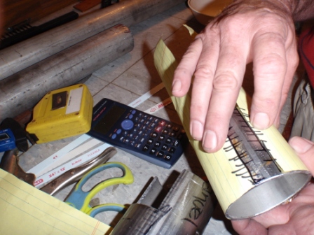
jparies 5 – Having calculated the required circumference and drawing it out on paper, Noel could calculate how much to cut out to reduce the size of the tubing for a snug fit over the rudder stock.

OLYMPUS DIGITAL CAMERA
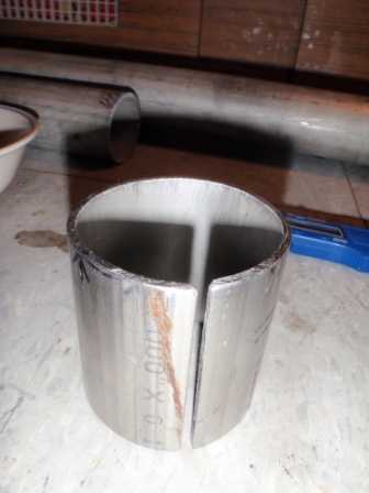
jparies 6 – Reducing 3 inch tubing to required diameter

OLYMPUS DIGITAL CAMERA
jparies 7 – Monitoring the shrinking process
OLYMPUS DIGITAL CAMERA
jparies 8 – Just about there, it is going to be a adjustable sleeve, so that the tiller can be firmly fasted to the rudder stock and eased for removal.
OLYMPUS DIGITAL CAMERA
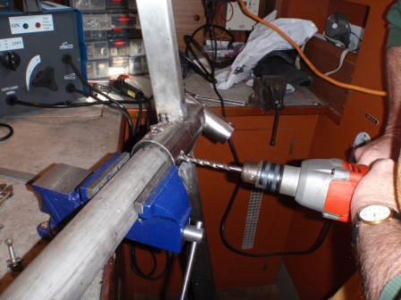
jparies 9 – The human drill press. Noel drilling through the new tiller head, into the new rudder stock extension. The bolts in place on top of the tiller head tighten against the inner sleeve to clamp firmly onto the rudder stock. (Noel recommends a drill-press).

OLYMPUS DIGITAL CAMERA
jparies 10 – Bits of scrap wood, one of which was promoted up from anti-foul stirrer, to form the rudder stock bearing mounting board.
OLYMPUS DIGITAL CAMERA
jparies 12 – Unfortunately, directly above the rudder stock is a hatch, another problem to overcome. Hence the need for the bearing mount board, which is positioned directly under the hatch.

OLYMPUS DIGITAL CAMERA
jparies 13 – Rudder stock extension bearing mount clamps, being fabricated out of flat bar.

OLYMPUS DIGITAL CAMERA
jparies 14 – The bearing mount board

OLYMPUS DIGITAL CAMERA
OLYMPUS DIGITAL CAMERA

OLYMPUS DIGITAL CAMERA

OLYMPUS DIGITAL CAMERA

OLYMPUS DIGITAL CAMERA
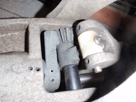
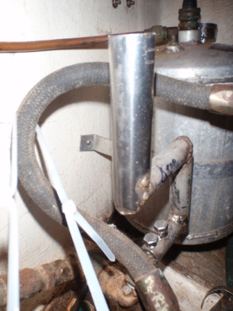
jparies 15/16/17/18/19 – The hydraulic bypass valve is conveniently buried beneath hoses. Noel engineered a crankshaft type handle, which extends up through the aft cabin hatch forming the remote spindle. This enables the turning of the bypass valve 90 degrees on/off/on from the aft cockpit and additional lines added have given us dual control to the centre cockpit too.

OLYMPUS DIGITAL CAMERA
jparies 20 – Under the aft cabin stairs , you can just see the square rudder stock near the bottom.
OLYMPUS DIGITAL CAMERA
jparies 21 – The radar arch was a convenient support platform for Aries

OLYMPUS DIGITAL CAMERA
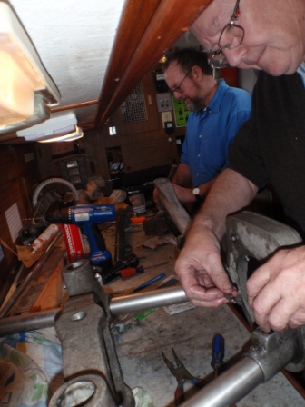
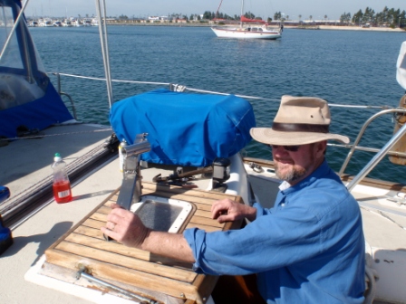
jparies 22 – Dad (Roy), “if I pull this, what happens?”

OLYMPUS DIGITAL CAMERA
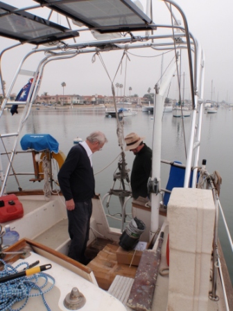
jparies 23 – Dad (Roy) (left), Noel (right). We figured if we did enough measuring and drew enough sketches, something would fall into place.

OLYMPUS DIGITAL CAMERA
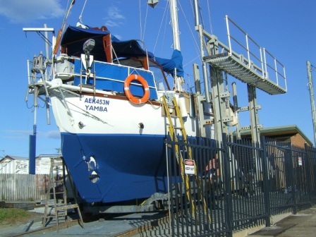
jparies 24 – Pyewacket II, will the Aries steer a 51’ boat

OLYMPUS DIGITAL CAMERA
jparies 25 – The swimming platform both helped and hindered. We had to extend the Aries frame beyond the platform, but it was very useful in construction.

OLYMPUS DIGITAL CAMERA
jparies 26 – The new rudder stock extension. The rudder stock is located under the stairs in the aft cabin.

OLYMPUS DIGITAL CAMERA
jparies 27 – The sparkling clean and lubricated Aries. The transom door is now firmly closed.
OLYMPUS DIGITAL CAMERA
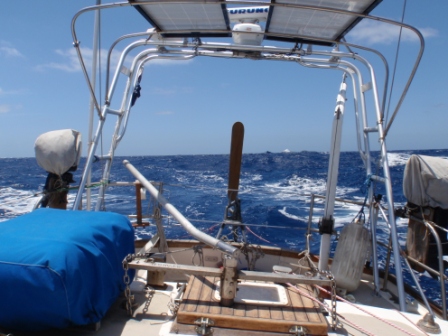
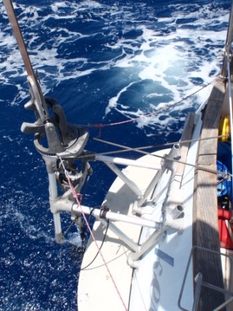
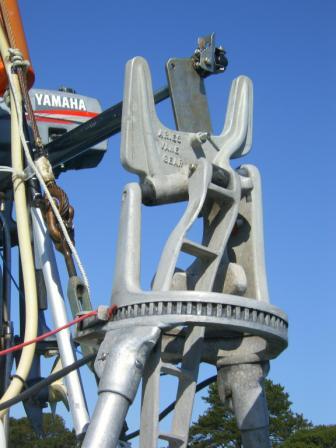
jparies 28 – The Aries in full flight. The emergency steering tiller is left permanently mounted at sea (angled left for ease of operation). At the end of the Aries tiller arms the control line chains slip over welded tabs enabling minute adjustment. From the Aries itself, the pink lines are the directional control, they extend into the centre cockpit via pulleys. The aft cockpit is busy with lines. The top of the remote spindle (for the bypass valve) is just behind the vane tiller arm on the hatch. A line wrapped around the top is extended into the centre cockpit for remote operation.
OLYMPUS DIGITAL CAMERA
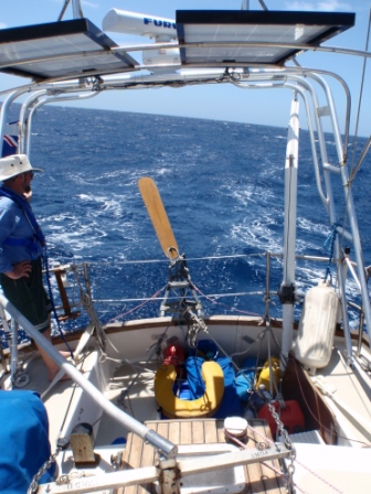
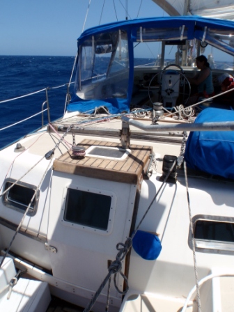
jparies 29 – This pulls this and that pulls that! Pulleys are fitted on to the control lines, roved to advantage to half the effort. A better view of the top of the remote spindle. You can see our aft cockpit is used as a boot!

OLYMPUS DIGITAL CAMERA
OLYMPUS DIGITAL CAMERA
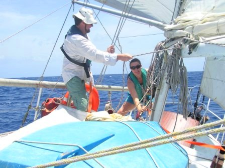
jparies 30/31 – Simply marvellous!
OLYMPUS DIGITAL CAMERA
jparies 32 – On top of the hatch, the top of the remote spindle (left) and the windvane tiller and the emergency tiller. The aft cockpit entrance door, at sea, can be slid open or closed but the hatch stays firmly shut.

OLYMPUS DIGITAL CAMERA
jparies 33 – Our sea bed at dawn, safely steered by Roy

OLYMPUS DIGITAL CAMERA
jparies 34 – Inside aft cabin, as it is in port. Stairs down and extensions and spindles removed. Our new batteries (now installed) are not working so hard with the electronic auto pilot now semi retired.
ELECTRIC COMPASS CONTROL
by Noel & Jackie Parry
“Wander” the trim tab style windvane was the creator of “Killer Tiller.” When using the home made steering gear we purchased with Mariah II, we wandered, side to side, so much so that the tiller took on an ankle breaking swing, side swiping anything that dare get in its path. The tiller took up a lot of the cockpit – these were dangerous times.
Enter “God”, “hero” or “our saviour”, more commonly known as stainless steel bracket made from bits and bobs. This bracket has steered us around the world in all weather; metres of rolling swells, opposing waves, washing machine conditions and howling gales; this little bracket has become a revered part of our boat. Well, let’s be sensible, the added attachment of our beloved Aries windvane and its phenomenal steering power was quite a help too.
Nature’s power
Windvanes, for steering your boat are a brilliant idea. They use the power of the water and the direction of the wind to steer your floating home. With a good sailing breeze these clever devices are reliable and can provide a good course, usually varying between 10°- 20°, maybe closer if the equipment is set up well and the conditions are ideal. More often than not, though, 15°-20° variations occur and sometimes more.
It is all pleasant enough if you are beam on or closer to the wind, the performance is not affected too greatly, however as you come off the wind, apparent wind speed and performance of the vane gear drops. Wandering side to side can have the boat losing both direction and speed. All of which is still far better, we think, than steering shorthanded around the clock. We hitch up our self-steering on leaving port and usually do not touch the tiller again until entering the next port.
Improving the marvellous
An adaptation to the reliance on wind is to connect the tiller pilot ram (Autohelm) to the windvane. Thus the enormous rudder loads that can happen are driven by the water powered vane, but the reliance on the sometimes fickle wind for direction, is eliminated and a more reasonable 5°-10° variation is achieved. Electric power consumption is kept to a minimum as the tiller pilot has an almost non existent load as it moves in and out. All the energy controlling the rudder is taken by the vane’s apparatus of levers, gears and swivels.
Temp to Perm
On our circumnavigation we fitted the tiller pilot to the vane thinking “well at least it will be nice for going down Brisbane River.” 45,000 miles later we now think it is marvellous all the time. Actually, on exceptionally narrow rivers (we like flat water) we set the tiller pilot directly to the tiller for pinpoint accuracy; the rest of the time, in any seas the bracket, tiller and windvane team work in harmony all the time.
Working Reliance
Mariah II’s aft hung rudder is like a barn door, wave loading can be high and an auto pilot ram directly mounted to the tiller would have to work hard. Most boats, that we met along the way, that had their auto pilots connected to any other part of their steering had failures. Quadrant mounted servo have to be enormous and use too much electricity even wheel mounted pilots failed, they spend too much time over compensating and thus working hard and using more power.
With our sails balanced, our tiller would be moving 50 mm side to side, it is hard to do that in “in the groove” sailing, even by hand. It’s remarkable to watch as your are sailing along at 6 knots in 3 metre seas, the wind on the quarter and the tiller barely moving. Even better is the fact that we barely waver off course, we all know that with two boats in one ocean it means a race, with our steering gear and course precision our odds for a smug win have improved!
What’s needed (if steering by tiller)
- A good windvane, Aries, Monitor, Fleming etc
- An electric tiller pilot with a remote control box. We use an Autohelm 4000, but a 1000 would be just as good as the loads are minimal.
- Mounting bracket, e.g ‘L’ shaped bracket bolted to the aft rail with a hole in it.
- Universal joint acting in 3 dimensions, this connects the pilot to the vane. Swivel and plate to connect the push-pull end to the “in place of the sheet of ply windvane”
SEE PICTURES- if that makes sense skip the following, if not bear with me – it sounds more complicated than it is.
Windvanes have two vanes, the top windvane and the bottom water vane. The top windvane which is removable and when in use is pointed into the wind, acts with two arcs of movement. One arc is the most obvious and rotates about the almost horizontal axle on the frame. The second arc, smaller and not readily noticed, rotates the vane on the vertical axis. So you don’t need to worry what all that means if the idea of a double acting universal joint is accepted. I finally did and it saved me a lot of staring into space.
So what is a double acting universal joint, besides something that may be found in Nimbin? All it is, is two “U” shaped brackets with two bolts, on bolt in the vertical and one in the horizontal.
The vertical bolt goes through the open parts of the first ‘U’ bracket and bolts through a hole drilled into the end of the pushy-pully thingy, the second bolt goes through holes drilled in the bottoms of the two U brackets. The second U bracket bolts directly and firmly onto a plate that replaces the ply windvane!! Got it??
Another thing, the length of the plate needs to be correct. The electric tiller pilot arm has a certain length of travel. The windvane frame has a certain range of travel. With the tiller pilot fully extended or retracted, the windvane should not hit its inbuilt stops otherwise you are trying to bend the whole expensive and much loved apparatus.
It all sounds complicated, but rest assured it is not. Just look at your windvane, dig out all your stainless steal bits and bobs, nuts and bolts, washers and lock nuts and have a go. Onboard Mariah II we have used bits and pieces that were lurking in the bilge for years and the system has worked faultlessly for eight years. I think I spent in total, 2 hours cutting and drilling (once I had figured out exactly what I needed, which can take forever) and like I said I thought it’d be good going down the Brissie River. It really has been one of the best two hours used for long term gain, peace of mind and general well being. The other time was when I got married, both are working just fine and come to think of it, I wouldn’t be able to have one with out the other!
Pictures

OLYMPUS DIGITAL CAMERA
P6060026 – We can’t win them all, friends fly off in front while crossing a bar on the East coast of America

P6290034 – We like flat water and the pilot ram on the Aries or the tiller works a treat (inland waterways of America)
OLYMPUS DIGITAL CAMERA
Perfect Sailing Days – Noel and I can work on deck rest assured Mariah will keep on course

SAMSUNG DIGITAL CAMERA
SA700351 – Our steering gear takes us right into the anchorage at Fatu Hiva in the Pacific Ocean, after 21 days sailing of winds between 5 – 40 knots, not once losing course.

SAMSUNG DIGITAL CAMERA
SA700552 – Once the sails are up and Mariah is balanced she sails herself
SAMSUNG DIGITAL CAMERA
SA700624 – Mariah’s large aft hung rudder, long keel and canoe stern all add to her stability at sea.

SAMSUNG DIGITAL CAMERA
SA700643 – Looking down on the set-up, noting vertical and horizontal bolts

SAMSUNG DIGITAL CAMERA
SA700649 – Looking down, the tiller arm is pivoting on the horizontal and vertical plane (contracted fully)

SAMSUNG DIGITAL CAMERA
SA700651 – When the ram is extended fully or contracted fully the Aries must not exceed its range of movement. (extended fully)
SA700660 – View of complete set up
